One digit requires 7 connections (wires) for all segments and 1 connection for common cathode (or anode). If I connect 6 digits to the MCU without any modification, I will need 7-segment x 6 digit = 42 connections . That means I need to use MCU with atleast 42 I/O pins. As you know, it is a waste for using a lot of MCU pins just for display. The required pins can be reduced dramatically by using a technique called Multiplexing.
Multiplexing
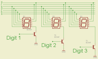
Multiplexing technique is based on the idea of Persistence of vision of the human eyes. The sample schematic of 3 digits multiplexing is shown below. Segment a-g of each digit are connected together. Each digit is switched on-off by controlling signal at Digit 1, Digit 2 and Digit 3. For example, if Digit 1 is ‘1’ , Digit 1 will be on. If Digit 1 is ‘0’, Digit 1 will be off. People will see all 3 digits display in the same time if each digit switch on and off fast enough.

3 Digits Multiplexed Schematic
By using multiplexing technique the number of required connections for 6 digits display is reduced from 42 pins to 7-Segment+6 digits = 13 pins Wow!! I can drive 6 digits 7-segment display by using just a PIC16F627A.
Programming
Multiplexing implementation is very similar to driving Led Dot Matrix. I use Timer0 interrupt for switching through each digit. Timer0 or TMR0 is an 8-bit timer which overflows every 256 (0xFF) counts. It’s known that the refresh rate above 50Hz would be enough for human’s eyes to see the display without recognizing the flickering. If I set TMR0 with 1:8 Prescaler, the multiplexing frequency will be
4MHz(internal OSC.)/4(working OSC)/8(prescaler)/256(max counts of TMR0)/6(number of digits) = 81.3 Hz which is good for a display.
Just an example, I have implemented (in Proteus) a 999999-second counter by using 6 Digits LED 7-Segment Multiplexing technique. There are 2 main components in the project, PIC16F627A or PIC16F628 and 6 x LED7-segment display. The schematic shows below. The crystal is 32.768KHz as usual. There is a 10KOhm pull up resistor at RA4 pin as this pin is an open-drain.

999999 counter schematic
Sourcecode for MikroC…
//PIC16F627A
//4MHz Internal OSC
//MUX by the MUC itself with Interrupt
//TMR0 .. check the prescelar+delay in scan routine as they are related
//punkky@gmail.com
unsigned short number [10] = {
0x5F, 0x06, 0x9b, 0x8f, 0xC6, 0xCd, 0xDD, 0x07,
0xDf, 0xCf
};
unsigned short digit [6];
unsigned short counter;
unsigned short shift_register;
unsigned short x1;
unsigned short x2;
unsigned short x3;
unsigned short x4;
unsigned short x5;
unsigned short x6;
unsigned short tick;
void interrupt ()
{
if (INTCON.T0IF)
{
//Scan digits with TMR0
INTCON.T0IF = 0;
if (counter == 5)
{
PORTA = number [digit [counter]];
Delay_us (500);
shift_register = 0x01;
PORTB = ~shift_register;
PORTA = 0x00;
counter = 0;
} else
{
PORTA = number [digit [counter]];
Delay_us (500);
shift_register = shift_register << 1;
PORTB = ~shift_register;
PORTA = 0x00;
counter ++;
}
}
if (PIR1.TMR1IF)
{
TMR1H = 0x80;
PIR1.TMR1IF = 0;
tick = 1;
//update current time
x6 ++;
if (x6 > 9)
{
x6 = 0;
x5 ++;
if (x5 > 9)
{
x5 = 0;
x4 ++;
if (x4 > 9)
{
x4 = 0;
x3 ++;
if (x3 > 9)
{
x3 = 0;
x2 ++;
if (x2 > 9)
{
x2 = 0;
x1 ++;
if (x1 > 9)
{
x1 = 0;
}
}
}
}
}
}
}
}
void main ()
{
//Digital I/O for PORTA
CMCON = 0x07;
TRISA = 0x00;
PORTA = 0x00;
TRISB = 0x00;
PORTB = 0x00;
//Internal Clock 4MHz
PCON.OSCF = 1;
counter = 0;
// Enable TMR0
OPTION_REG.T0CS = 0;
// Enable Prescaler
OPTION_REG.PSA = 0;
// PS0,1,2 = 010 = 3
// 3 means 1:8 prescaler
// 1:2, 1:4, 1:8, 1:16, 1:32, 1:64, 1:128, 1:256
OPTION_REG.PS2 = 0;
OPTION_REG.PS1 = 1;
OPTION_REG.PS0 = 0;
INTCON.T0IF = 0;
INTCON.T0IE = 1;
INTCON.GIE = 1;
INTCON.PEIE = 1;
T1CON = 0x0F;
TMR1H = 0x80;
TMR1L = 0x00;
// Enable TMR1 interrupt
PIE1.TMR1IE = 1;
shift_register = 0x01;
x1 = 0;
x2 = 0;
x3 = 0;
x4 = 0;
x5 = 0;
x6 = 0;
while (1)
{
if (tick)
{
tick = 0;
//update digits
digit [0] = x1;
digit [1] = x2;
digit [2] = x3;
digit [3] = x4;
digit [4] = x5;
digit [5] = x6;
}
}
}